


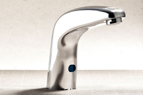

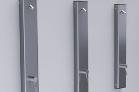



BIM is an acronym for 'Building Information Modeling' and is defined as the digital representation of the physical and functional characteristics of an object, whatever it is, and is composed of the 3D model where all the physical, performance and functional data of it are collected.
BIM, however, is not a new 3D representation format, but a technology that allows the creation of an informative and shared model containing useful information at every stage of design: such as technical drawings, building geometries, geographical location of objects, material properties, thermal characteristics, energy performance, installations, safety, maintenance and demolition, etc.
In our case, the information we would share would be related to the geometry of the fittings, the properties of the materials used, information on the technical elements and all the technical specifications in order to be able to help the designer in the development of the project.
A step forward in design
To date, there are four levels of BIM, and they are as follows:
- Level 0- Standardised CAD: Basically it is the organisation of work in a traditional way.
- Level 1- Solitary BIM: the parametric design and data management method is used internally without establishing any type of collaboration with other professionals.
- Level 2 - Collaborative BIM: In this case there is collaboration between those involved in the design and information is shared through a common file.
- Level 3 - Shared BIM: all professionals work simultaneously on the same model so that updates are received in real time.
In the design industry, there are levels of detail(LOD - Level Of Detail) that define the level of accuracy of the information contained within the BIM model. They represent a reference point that allows all those involved to build the BIM model with the same degree of definition and accuracy of content.
There are five LODs and they are as follows:
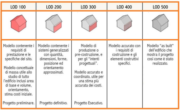
- LOD 100: the element is represented in a generic manner and further information about the model element can be obtained from other sources.
- LOD 200: the element is represented with generic quantity, size, shape, position and orientation.
- LOD 300/350: The feature is represented with correct quantity, size, shape, position and orientation.
- LOD 400: Item is depicted with correct quantity, dimensions, shape, position and orientation and details of manufacture, assembly and installation.
- LOD 500: the element faithfully reflects reality, and is a verified representation in terms of quantity, size, shape, position and orientation.
To stay on topic, the Italian standard that refers to the above-mentioned LODs is UNI 11337-4:2017 and they are defined according to the scale shown below:
- LOD A: the entities are represented graphically through a symbolic geometric system or a representation of a kind taken as a reference without geometric constraints. Quantitative and qualitative characteristics are indicative.
- LOD B: entities are virtualised graphically as a generic geometric system or an encumbrance geometry. Qualitative and quantitative characteristics are approximate.
- LOD C: Entities are virtualised graphically as a defined geometric system. The qualitative and quantitative characteristics are defined generically in compliance with the limits of the regulations in force and the reference technical standards and referable to a plurality of similar entities.
- LOD D: entities are graphically virtualised as a detailed geometric system. Qualitative and quantitative characteristics are specific to a defined plurality of similar products. The interface with other building-specific systems is defined, including approximate manoeuvring and maintenance dimensions.
- LOD E: Entities are virtualised graphically as a specific geometric system. Quantitative and qualitative characteristics are specific to a single production system related to the defined product. The level of detail related to manufacturing, assembly and installation is defined, including specific manoeuvring and maintenance dimensions.
- LOD F: The objects express the on-site verified virtualisation of the specific production system executed/constructed. The quantitative and qualitative characteristics are those specific to the individual production system of the product laid and installed. The management, maintenance and/or repair and replacement interventions to be carried out throughout the life cycle of the product are defined for each individual product.
- LOD G: objects express the updated virtualisation of the state of an entity at a defined time. Management, maintenance and/or repair and replacement interventions to be performed throughout the life cycle of the work are defined for each individual product.
Benefits and the future
BIM helps clients, architects, engineers in providing information to manage an infrastructure throughout its life cycle, reducing the cost of operations, as well as maintenance interventions.
The use of BIM is increasing in infrastructure projects, prompting many players in the industry to adopt it to achieve greater competitiveness and win new work.
Projects using a BIM-based approach can boast a number of advantages, including:
- Less project rework.
- Fewer errors.
- Better collaboration between the parties involved.
- Leaner and smoother maintenance.
- Proper and sustainable resource management.
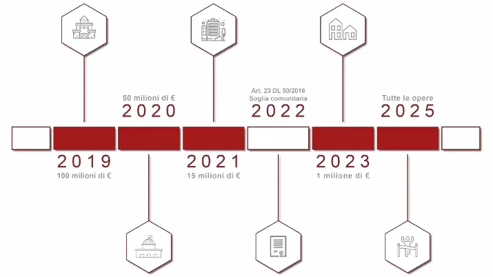
So much so that public administrations are increasingly imposing the use of BIM in their projects. In fact, in Italy, with the approval of DM 560 of 2017, the methods and timeframes for the gradual introduction of the BIM method for construction and infrastructures have been established, up to full use in 2025 (unless extended and/or derogated).
Having said that, BIM is a tool that is gaining an increasing foothold in our working lives, giving us a helping hand in simplifying the work of others for greater precision and speed in the design and development of small and large works. You can find our BIM on each product page.
by Francesco Balbo
Technical Office